How to Power Electronics
Overview
This tutorial will cover the various ways you can power your electronic projects. It will go into some detail about voltage and current considerations you may want to make. It will also go into the extra considerations you have to make if your project is mobile/remote or, in other words, not going to be sitting next to a wall power outlet.
If this is truly your first electronic project, you have the option of reading through this tutorial or sticking with the recommended supply for the project or development board of your choice. The SparkFun Inventor’s Kit contains the USB cable you need for power and works fine for all the projects in the kit as well as many more advanced projects. If you’re feeling overwhelmed, that kit is the best place to start.
Suggested Reading
Here are related tutorials you may want to check out before reading this one:
Ways to Power a Project
Here are some of the most methods used for powering a project:
- AC to DC power supplies (like a computer or laptop would use)
- Variable DC bench power supply
- Batteries
- Via a USB cable
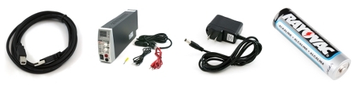
Four common ways to supply power to your project
Which option should I pick to power my project?
The answer to this question largely depends on your project specific requirements.
If you’re starting off with the SparkFun Inventor’s Kit or another basic development board, you will likely just need a USB cable. The SparkFun Redboard is an example that requires only a USB A to B cable to supply the power to run the example circuits in the kit.
If you’re in the business of building projects and testing circuits regularly, acquiring a variable DC bench power supply is highly recommended. This will allow you to set the voltage to a specific value depending on what you need for your project. It also buys you some protection as you can set a maximum current allowed. Then, if there is a short circuit in your project, the bench supply will shut down hopefully preventing harm to some components in your project.
A specific AC to DC power supply is often used after a circuit is proven. This option is also great if you often use the same development board again and again in your projects. These wall adapters usually have a set voltage and current output, so it’s important to make sure that the adapter you choose has the correct specifications as the project you will be powering and to not exceed those specifications.
If you want your project to be mobile or based in a remote location away from where you can gather AC wall power from the grid, batteries are the answer you’re looking for. Batteries come in a huge variety so be sure to check out the later parts of this tutorial so you can figure out precisely what to choose. Common choices include rechargeable NiMH AA’s and lithium polymer ion.
Voltage/Current Considerations
How much voltage do I need for project X?
This depends largely on the circuit, so there is no easy answer to this question. However, most microprocessor development boards like the Arduino Uno have a voltage regulator on board. This allows us to supply a voltage in a specified range above the regulated voltage. A lot of microprocessors and IC’s on development boards run at 3.3 or 5 Volts but have voltage regulators that can handle anywhere from 6V to 12V.
The power comes from a power supply and is then regulated closely by a voltage regulator so that each chip is powered at a consistent voltage even when the current draw may fluctuate at different times. Here at SparkFun, we use 9V power supplies for many of our products that operate in the 3.3V to 5V range. However, to verify what voltages are safe, it is recommended that you check the datasheet for the voltage regulator on the development board to see what voltage range is recommended by the manufacturer.
How much current do I need for project X?
This question also depends on the development board and microprocessor you’re using as well as what circuits you plan on connecting to it. If your power supply cannot give you the amount of juice the project needs, the circuit may start acting in a strange, unpredictable way. This is also known as a brown-out.
As with voltage, it’s recommended to check the datasheets and estimate what the different bits and pieces of the circuit might need. It’s also better practice to round up and assume your circuit will need more current than to not provide enough current. If your circuit includes elements that require massive amounts of current, like motors or large amounts of LEDs, you may need a large supply or even separate supplies for the microprocessor and the extra motors. Again, it’s always in your best interest to get a power supply rated for a higher current and not use the extra than to have a supply that can’t provide enough.
Have no idea how much current your project draws?
Once you’ve been playing with circuits for a while, it will be easier to estimate the amount of current your project requires. However, the common ways to figure it out experimentally are to either use a variable DC power supply that has a readout for current or to use a digital multimeter to measure the current going to your circuit while it’s running. If you don’t know how to measure current with a multimeter, please see our multimeter tutorial.
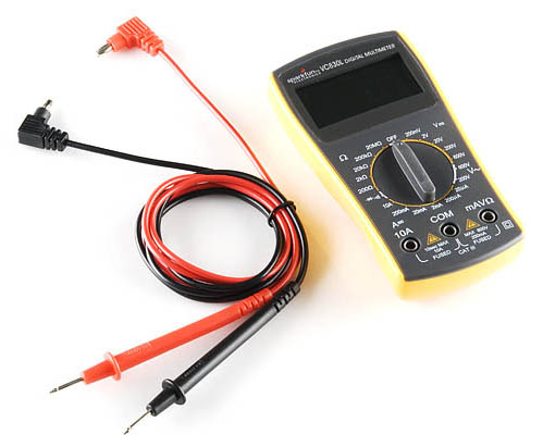
Digital Multimeter
We highly recommend having a DMM in your electronics toolbox. It’s great for measuring current or voltage.
Connections
How do I connect my battery or power supply to my circuit?
There are many ways to actually connect a power supply to your project.
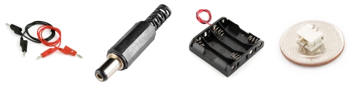
Common ways to connect a power to your circuit
Variable benchtop power supplies commonly connect to circuits using banana jacks or wires directly. These are also similar to the connectors found on the multimeter probe cables.
Many projects are built on a breadboard first, as a prototype, before they become a final product. There are numerous ways to power your breadboard circuit, many of them involving a the same connectors mentioned here.
Once a project is past the prototyping phase, it will usually end up on a PCB. One of the most common power connectors used on a finished PCB, in both consumer electronics and hobby electronics alike, is the barrel connector, also know as a barrel jack. These can vary in size, but they all function the same and provide a simply, reliable way to power your project.
Batteries are generally held in a case that holds the batteries and connects the the circuit via wires or a barrel jack. Some batteries like Lithium Polymer Ion batteries often use a JST connector.
To learn more about different power connectors, please see our connectors tutorial.
Remote/Mobile Power
Which battery should I choose?
When you’re powering a remote circuit, the same issues of finding a battery that delivers the proper voltage and current still apply. Battery life, or capacity, is a measure of total charge the battery contains. The capacity of a battery is usually rated in ampere-hours (Ah) or milliampere-hours (mAh), and it tells you how many amps a fully charged battery can supply over a period of one hour. For example, a 2000mAh battery can supply up to 2A (2000mA) for one hour.
Battery size, shape, and weight is also something to consider when making your project mobile, especially if it’s going to be on something that flies like a small quad-copter. You can get a rough idea of the variety by visiting this wikipedia list. Learn more about battery types in our battery technology tutorial.
Batteries in series and parallel
You can add batteries in series or parallel to produce the desired voltage and current needed for your project. When two or more batteries are placed in series, the voltages of the batteries are added together. For example, lead-acid car batteries are actually made out of six single-cell lead acid batteries tied together in series; the six 2.1V cells add up to produce 12.6V. When tying two batteries in series, it’s recommended that they be of the same chemistry. Also be wary of charging batteries in series as many chargers are limited to single-cell charging.
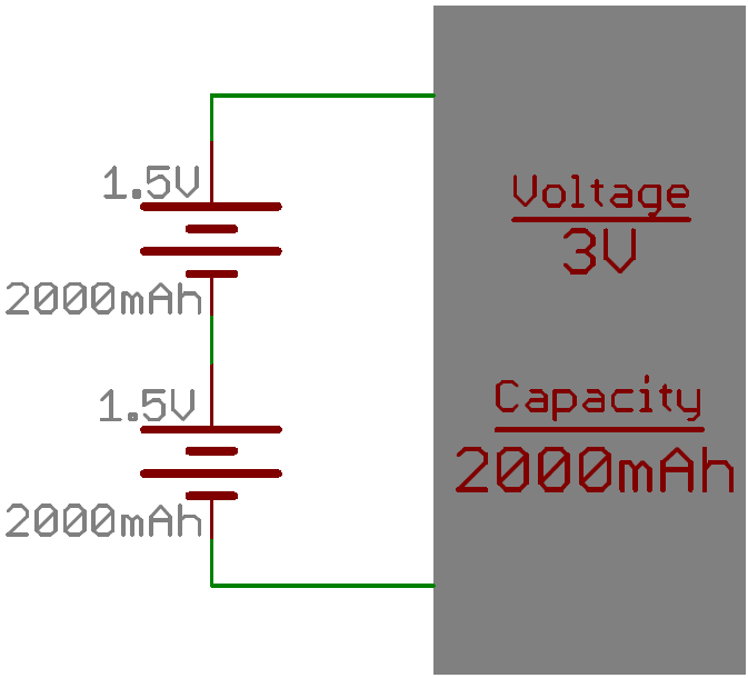
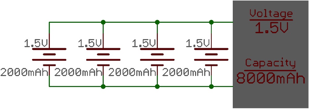
When you connect two or more batteries in parallel, the capacities add. For example, four AA batteries connected in parallel will still produce 1.5V, however the capacity of the batteries will be quadrupled.
How much battery capacity do I need for my project?
This question is easier to answer once you have determined the amount of current that your circuit normally draws. In the following example, we will use estimation. However, it is encouraged that you measure current draw of your circuit using a Digital Multimeter to get accurate results.
As an example, let’s start with a circuit, estimate its current output, then select a battery and calculate how long it the circuit will run on battery power. Let’s choose a ATmega 328 microcontroller to be our brains for the circuit. It draws about 20mA under normal conditions. Let’s now connect three red LED’s and the standard 330 ohm current limiting resistors to digital I/O pins of the microcontroller. In that configuration, each LED added makes the circuit draw about 10mA more current. Now let’s connect two Micro Metal motors to the microcontroller as well. Each one of these uses approximately 25mA when turned on. Our total possible current draw is now:

Let’s choose a standard alkaline AA battery for this because it has more than enough current capability (up to 1A), has a decent battery capacity (usually in the range of 1.5 Ah to 2.5Ah), and is very common. We’ll assume the average is 2Ah for this example. The downside to using a AA is it only has a 1.5V output, and, since the rest of our components will run on 5V, we need to step up the voltage. We can use this 5V step-up breakout to get the voltage we need, or we can use three AA batteries in series to get us close to the voltage we need. Three AA’s in series gives us a voltage of 4.5 V (3 times 1.5V). You could also add another battery for a total of 6V and regulate the voltage down to what your circuit requires.
To calculate how long a circuit will last on battery power, we use the following equation:

For a circuit powered by 3 AA’s in parallel that’s connected to a circuit with a constant 100mA current draw, this translates to:
We would ideally get 60 hours of battery life out of these three alkaline AA’s in this parallel configuration. However, it’s good practice to ‘derate’ batteries, which means to assume you’re going to get less than ideal battery life. Let’s conservatively say that we’ll get 75% of the ideal battery life, and therefore about 45 hours of battery life for our project.
Battery life can also vary based on the actual current draw amount. Here’s a graph from an Energizer AA battery showing its expected battery life based on constant current draw.

Energizer AA, Current vs Battery Life
This is just one of the numerous configurations you could use to power your project remotley.
Resources and Going Further
You should now know the most common ways to power your circuit and how to figure out which way is best for you depending on your your project’s specific requirements. You can make a better judgment now based on current, voltage, connector, and mobility considerations for your project.
If you would like to learn more about prototyping circuits, please check out our breadboard tutorial: