Using the GPIO Pins with Scratch on Raspberry Pi
Introduction
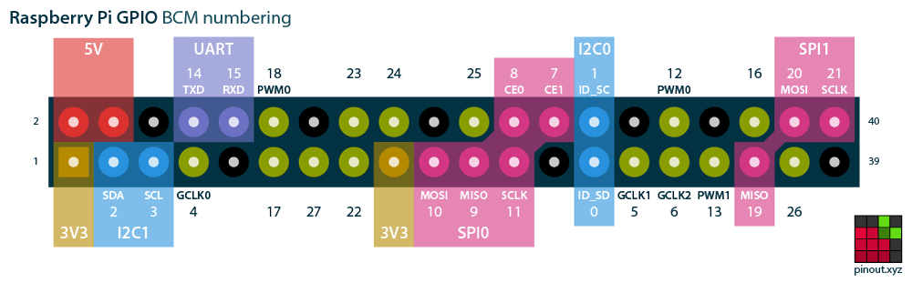
The standard Raspberry Pi Model B, and B+ have a 2x20 pin connector that provides access to connections you can use to turn on LEDs, read button presses, spin motors, and more! These pins are often referred to as General Purpose Input \ Output (GPIO) Pins. The diagram above shows the pin numbers. Not all pins are used and not all pins are in order.
To connect an LED to these pins, you can use a Male to Female jumper wire to connect to a breadboard, but it's often difficult to count or recall which pin is which.
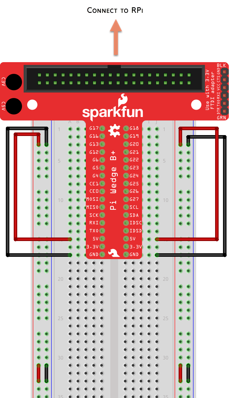
To make things easier, we've developed the Pi Wedge breakout board. This connects using a 40 pin ribbon cable directly to a breadboard. The pins are spaced to fit directly over the center-line ditch of a standard breadboard and provide easy access to the GPIO pins on the Raspberry Pi.
On the right-hand side of the board is a six-pin header for connecting to the Raspberry Pi via serial. This can be useful if you're using the Raspberry Pi 'headless' (without a monitor, keyboard, or mouse).
Setup
The ribbon cable is keyed so that it can only be inserted in one direction. Connect one end of the ribbon cable to the Pi Wedge so that the ribbon points up and the key lines up. Connect the other end to the Raspberry Pi. The key should point toward the center of the Raspberry Pi.
The Pi Wedge will occupy the top 17 rows of a breadboard. Carefully insert the Pi Wedge into the top-most rows of the breadboard. Because you'll probably use these, connect the 5V and GND to the power rails on the breadboard.
Note: the power rails on the full-size breadboards are often split between the upper half and the lower half. You may need to add a jumper for power and ground to make sure that the power rails are connected throughout the board.
Exercise 1 - Using the breadboard.
Before we start building circuits and programming on the Raspberry Pi, let's first explore using the solderless breadboard. The solderless breadboard is a prototyping tool that allows us to connect wires together without solder and without physically twisting the wires together.
The breadboard is split in half, divided by a ditch - left and right. The left side is completely separate from the right side. The breadboard consists of a bunch of holes where you can insert a wire or a component. The center part of the breadboard is organized into rows of five holes each. Behind each of these rows is a single metal clip that will connect together any wires that are inserted into this row. On the sides of the breadboard are two vertical columns (sometimes marked with a + and a -). These are called power rails. The vertical columns are connected vertically. We often connect Power and Ground to these two columns to provide access to power for building your circuit. These are similar to a power strip you might use in your house.

Building a simple LED circuit.
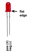
An LED is a special component that lights up when electricity is passed through it. An LED, however, only works when electricity flows in a certain direction. It as what we call a polarity. There are two legs - one is longer than the other. The shorter leg (cathode) is negative. And, if you look carefully at the plastic part, you'll notice a flat edge on this side. The longer leg is called the anode and is positive.
LEDs have very little resistance, and because of this, they use very little power and make really great light sources. However, because there's little resistance, we need to include a current limiting resistor when we use an LED in a circuit.
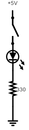
Here is a diagram for a circuit that you're going to build. The symbol for the LED is the triangle-shape with a line and circle. It has arrows pointing away from it showing 'light' is emitted when electricity flows through this device.
The squiggly symbol after that is called a resistor. Resistors come in various sizes that indicate how much it slows down current flow. Resistance is measured in units called ohms. The resistor we're going to use is a 330 ohm resistor. This limits the current to about 9 mA.
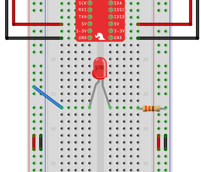
Let's build the circuit! Use the diagram on the right to build a simple LED circuit on the breadboard. Make sure that the long leg of the LED is connected to the 5V side. Here, we're using the ditch to separate the two legs of the LED.
Rinse & Repeat. Now see if you can add more LEDs to your board. The practice of using the breadboard is essential to working with electronics. Pay careful attention to where the wires are plugged in. If a wire is off by a single row, it may not be connected to your circuit.
Parallel and Series
In electronics and in circuit building, you may hear the phrase parallel and series. This is used to refer to the relative position of components in a circuit. When two or more components are in-line, we refer to them as connected in series. When components are connected so that both ends are connected together, we call this parallel. Here are a few examples using boxes as examples:
| A, B, and C are connected together in series. |  |
| A, B, and C are connected together in parallel. |  |
| Combo - A is in series with the combination of B and C in parallel. | |
Using a Push Button Switch
This is important when using switches. We are going to use a switch to open and close a circuit. There are a few symbols used to represent switches, but the most basic one looks like the symbol above.
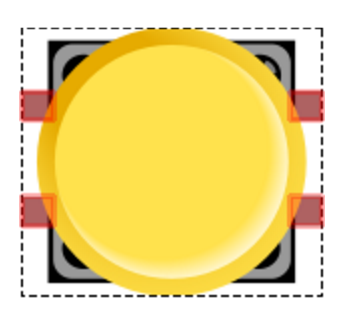
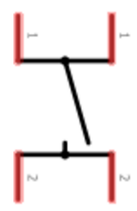
In our circuit, we're going to use a momentary push-button switch. This device closes the circuit when the button is pressed, and then springs back up when you release the button. These push button switches have four legs and are designed to straddle the ditch of a breadboard. The left and right legs are connected internally.
Sometimes this symbol is used to represent the push button switch. It shows the internal connections of the legs on the push button.
We are going to connect the switch is in-line (in series) with the LED circuit, it can control the flow of electricity to the LED. What would happen if you connected the switch in parallel with the LED?
Here is a circuit diagram and a drawing of the circuit:
Your turn!
For each of these, draw a sketch of the circuit diagram (using the appropriate symbols) for each circuit you build.
- Wire up a button so that it's in parallel with just the LED. What happens when you push the button?
- Wire up a circuit so that the switch turns on two LEDs at the same time.
- Wire up a circuit that requires two buttons to be pressed so that the circuit turns on.
Exercise 2 - GPIO control using Scratch on the Raspberry Pi
Reference: https://www.raspberrypi.org/documentation/usage/scratch/gpio/README.md
Setup
This initializes the GPIO server application that listens to broadcasts and updates variables in Scratch. Broadcast message: gpioserveron. |
There are basically three broadcast commands used to configure and control the GPIO pins on the Pi. These are described below and used in the examples that follow:
config[#][input/output/outputpwm] - [#] indicates the GPIO pin, [input/output/outputpwm] indicates the configuration setting of the pin. All pins defined as inputs will appear as sensor blocks and can be used accordingly.
gpio[#][on/off/high/low] - [#] indicates the GPIO pin, [on/off/high/low] indicates the desired state of the pin.
gpio[#]pwm[value] - [#] indicates the GPIO pin, [value] represents a value from 0 - 1024 to control things like the brightness of an LED or motor speed.
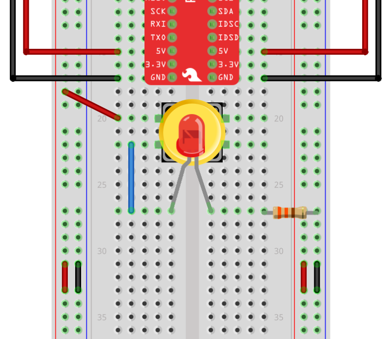
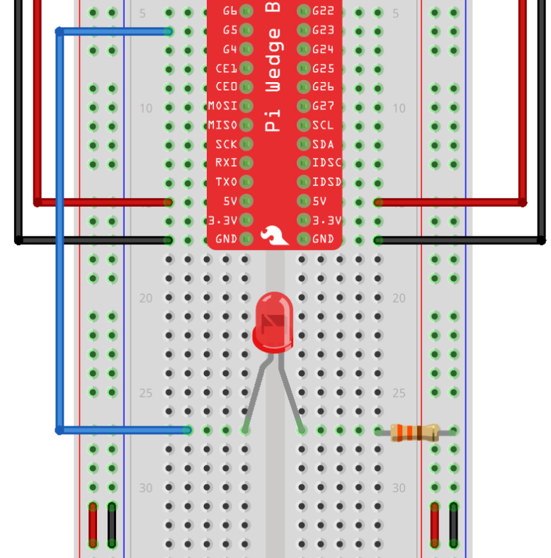
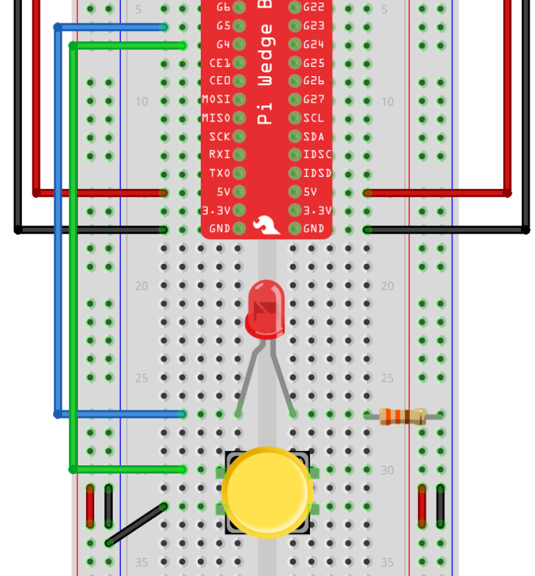
Connecting an External LED to the GPIO pins To control the LED in code, we need to connect it to one of the GPIO pins. The Raspberry Pi can control whether or not these pins have power (high / low / on / off). Connect up an LED to GPIO pin G5 on the Pi Wedge. Now you can turn the LED on and off using a broadcast message: gpio4on or gpio4off. |
 |
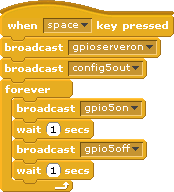
Blink!! You can string together a sequence of broadcast messages to create the following script. Press the space key to watch what happens! |
 |
Sweetheart... Modify the code example from the blink to see if you can create a pattern that resembles a heartbeat. Hint: Right-click on a stack of blocks and click duplicate to create a copy of the blocks. The time values in the wait block can accept both whole numbers and decimal values. |
Morse Code Tester . . . - - - . . . Morse code is a sequence of short and long beeps, blips, or blinks to represent characters. The symbols . . . - - - . . . are universally known for S-O-S in morse code. Re-create your name in morse code using the blinking pattern. To clean up your code, create custom broadcast messages for a dot and a dash.  |
Mo' LEDs Use the example wiring diagram above to add more LEDs to your circuit. Add at least 5 LEDs and sequence these to each turn on one at a time! What kinds of sequences can you create? |
|
Light Sculpture Challenge Extend the LEDs from the breadboard using Male-Female jumper wires. With the LEDs free from the breadboard, you can now integrate these into your very own sculpture. Make sculpture using cardboard, paper, plastic cups, or whatever you can find. Sequence the LEDs to flash, blink, or fade to give your sculpture some style. Every piece of art must have a name. Be sure to come up with a name for your creation and describe your inspiration for this project in your notebook. |
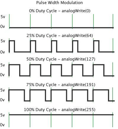
Exercise 3 - Need more control?
We've shown you how to turn LEDs on and off with a few simple commands. You can also set the LEDs to a half brightness or mid-level brightness using a technique called PWM (pulse-width-modulation). The Raspberry Pi is a digital device. It's only capable of turning pins ON and OFF, but it can also do this really, really fast. It can turn an LED on and off so fast you don't see it blink. The Raspberry Pi flashes the pin at 800 Hz - that's 800 times per second! By changing the duty cycle (the amount of time the pulse is on compared to the amount of time the pulse is off), makes the LED look either brighter or dimmer. The image to the right illustrates how this works.
To control the brightness of an LED, you need to set it up as an outputpwm pin.
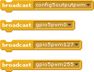
To set the brightness, use the broadcast command: gpio[#]pwm[value] -- [#] indicates the GPIO pin, [value] indicates the duty cycle of the PWM signal ranging from 0 to 255. These three blocks set pin 5 off, half brightness, and then full brightness.
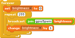
Fading LED Example Create a variable called brightness - you'll use these a combination of these blocks from the palette. The completed code is shown on the right. Connect up an LED to GPIO pin G5 on the Pi Wedge. Now you can turn the LED on and off using a broadcast message: gpio4on or gpio4off.
|
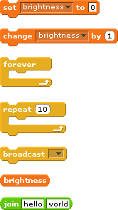
Code Block Examples This code snippet sets brightness to 0, then repeats 255 times
|
Exercise 4 - Using Inputs / Reading Button Presses
The Raspberry Pi is a digital device, so it can only read whether a pin is HIGH or LOW. We can connect a push-button switch in one of two configurations. The first is the standard configuration. When you push the button, it will connect the GPIO pin to ground (GND). The default state of the pin is HIGH (1).
To configure GPIO pin 4 as an input, send a broadcast message: config4input If you have the gpioserveron, this will create a new 'sensor' option called gpio4. 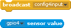
Here's a quick example of controlling the LED using the button press. How would you modify this so that the LED is normally on and turns off when you press the button? 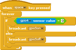 |
 |
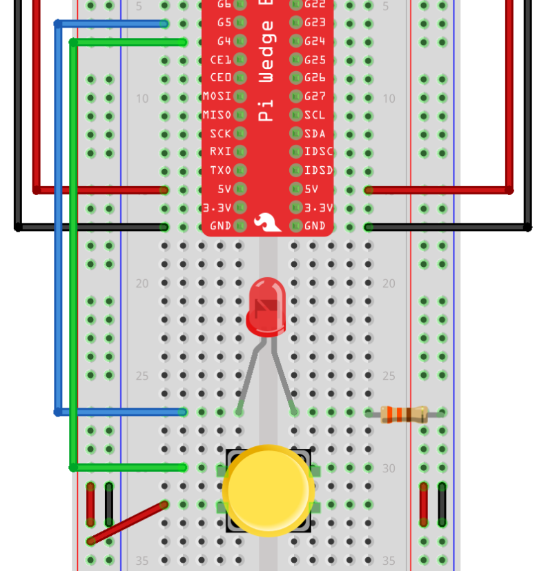
Method 2 - configure the input so that the default state is LOW (0). You can also configure the pin as an inputpulldown.
Configure the pin to be default LOW (0): Now, instead of connecting the other side of the button to the Ground (GND) rail, connect it to the 5V rail. When you push the button, you'll connect the pin to 5V (HIGH or 1). How does this change the logic you used in your original script? Now you can build your own game controller to move the sprite around, play notes, and other fun games in Scratch! Pick the configuration that makes most sense for you! |
 |

Additional/Bonus Features
These are a set of additional messages and features that are enabled in Scratch on the Raspberry Pi.
Control of all pins
You can control all of the (output) pins using the broadcast message allon or alloff.

Servo Motors
Servo motors are special types of motors that move to a specific angle based on the signal that it receives. Servo motors have three wires - White, Red, and Black. Connect the white wire to a GPIO pin. Connect Red to 5V and Black to GND.
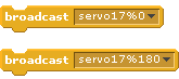
This feature is still a little buggy, but you can control a servo motor by broadcasting the message: servo[#]%[angle] -- [#] indicates the GPIO pin, [angle] indicates the desired rotation angle from 0 to 180. In my most recent tests, it only moves about 45 degrees rather than the full 180.
Using Variables to control pins
Rather than using broadcast messages, you can also control the pins by changing the value of variables. For example, create a variable called gpio5, and set it equal to 1 to turn GPIO5 on or 0 to turn the pin off. Scratch has a 'feature' where it only updates changes in variables to the GPIO pins. If you try to set a variable to 0 and it's already 0, it won't update the hardware pin.
Other Commands
The team at Cymplecy have a visual command guide for other features here. Based on the most recent tests, I have not found that all of these commands are still supported, but it is a nice reference for additional features and functionality using ScratchGPIO.